Fabric for MODO チュートリアル
プロシージャルメッシュ
In this tutorial you will learn how to create a procedurally driven mesh within MODO. This is a very powerful concept and will allow you to create portable procedural assets driven by any KL extension, for example an Alembic reader or a Bullet Softbody simulation. We’ll focus on the basics in this tutorial to get you started.
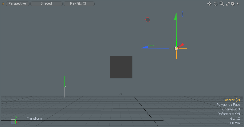
- Start with a new MODO scene.
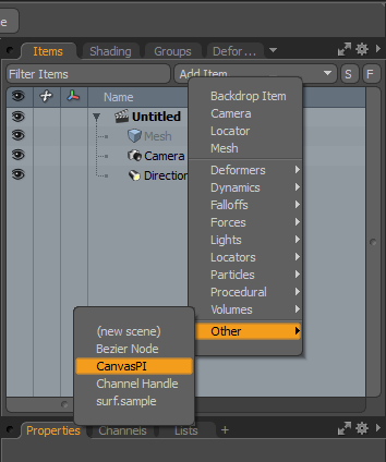
- Add a CanvasPI item to the scene by using the “Add Item” drop down:
- Open the Canvas UI by clicking on the button “Open Canvas” in the item’s property page.
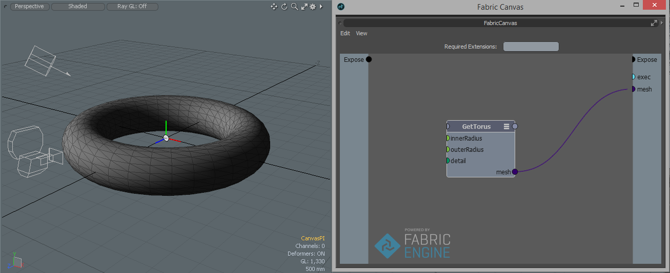
- Click into the main area (where you can see a little “Press TAB to insert nodes”) and then press the TAB key. This will start the tab search. Enter “gettor” and press return. A “GetTorus” node is added to your graph.
- Now expose the output of the “GetTorus” node: left-click on the “mesh” port and then drag it to the black “Expose” port on the right and release the mouse button. Your graph should now look like this and you should see a torus in the viewport:
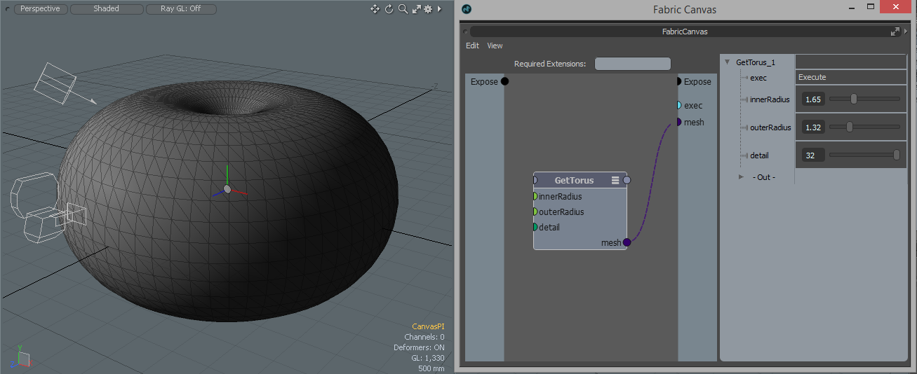
- To tweak the parameters (= the input ports) of the “GetTorus” preset simply double-click on it and the value editor will appear on the right. You can make it a bit wider if needed by clickiing and dragging the left border of the value editor. Then play around with the parameters to get a different looking torus:
Driving a Null - Linear Interpolation
Here you will learn how to drive the kinematic of an item. This is the first step towards using Canvas for rigging.
- Start with a new MODO scene.
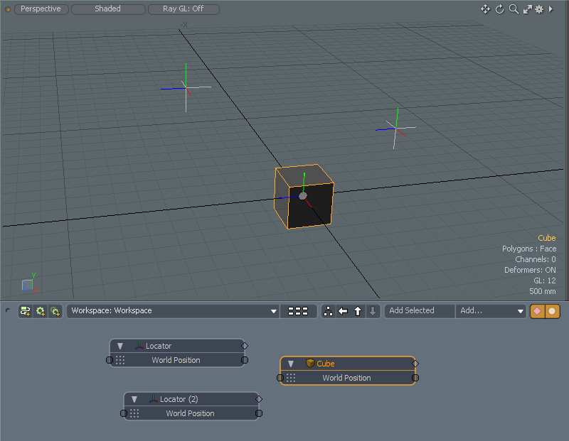
- Get two locators and place them somewhere in your scene.
- Get a cube (Item -> Primitive -> Cube).
- Select both locators and the cube and then click on “Add Selected” in the schematic view.
- Add the “World Position” channels to all three items. Things should look like this now:
- Now add a “CanvasIM” item to the schematic view by choosing “Add ... -> Channel Modifyer -> Other -> CanvasIM”.
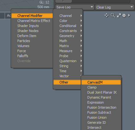
- After a short moment the item will show up in the schematic view.
- Open the Canvas UI by clicking on the button “Open Canvas” in the item’s “Properties”.
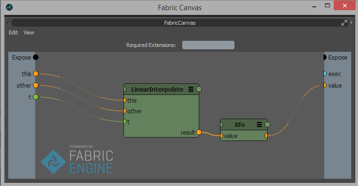
- Use the tab search to add a “Func.LinearInterpolate” node.
- Use the tab search to add a “Constants.Xfo” node.
- Connect the “Result” port with the “Value” port. Note how the “LinearInterpolate” node now has all ports of type “Xfo” (‘Xfo’ stands for’ transformation’).
- Expose all the input and output ports so that your graph looks like this:
- Finally connect things up in the schematic view like this:
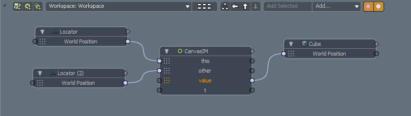
- The cube should now be located at the position of the first locator. Set the value of the “t” channel of the CanvasIM item to “0.5”. Now the cube should be exactly between the two locators.
- Done ... and time to play! Select one of the two locators and move it around. The cube will always stay between the two locators: